Manual Transmission Components: A Comprehensive Overview
This guide unveils the intricacies of manual transmissions, detailing parts diagrams and functionalities for Subaru models, offering a comprehensive exploration of its operational aspects.
Manual transmissions represent a cornerstone of automotive engineering, offering a direct mechanical link between the engine and wheels. Unlike automatic systems, they empower drivers with complete control over gear selection, influencing vehicle speed and power delivery. This control stems from a system of gears, shafts, and a clutch, meticulously designed to transfer rotational force efficiently.
Understanding these components is crucial for both drivers and mechanics. A manual transmission parts diagram serves as an invaluable resource, illustrating the arrangement and interaction of each element. This knowledge facilitates effective troubleshooting, repair, and even performance enhancement. The Subaru manual transmission, in particular, boasts a robust design, demanding a thorough understanding of its specific features and functionalities, as detailed in accompanying user manuals.
Essentially, a manual transmission allows the driver to manually select the appropriate gear ratio for varying driving conditions, optimizing engine performance and fuel efficiency.
Historical Development of Manual Transmissions
The evolution of manual transmissions mirrors the history of the automobile itself. Early vehicles relied on simple, direct-drive systems, quickly proving inadequate for varying speeds and terrains. The late 19th and early 20th centuries witnessed the emergence of rudimentary gearboxes, often employing complex lever systems for gear changes. These early designs, while functional, lacked the smoothness and efficiency of modern systems.
Significant advancements occurred throughout the 20th century, including the introduction of synchronized gearboxes, dramatically improving shift quality. Understanding the historical context aids in appreciating the intricacies of current manual transmission parts diagrams. Subaru, like other manufacturers, continually refined its transmission designs, focusing on durability and driver engagement.
The development of more precise manufacturing techniques and materials allowed for smaller, lighter, and more robust transmissions, ultimately shaping the systems we see today. User manuals document these improvements.
Advantages and Disadvantages of Manual Transmissions
Manual transmissions offer a unique driving experience, prized for driver control and engagement. A key advantage is increased fuel efficiency, as drivers directly manage power delivery. They also generally boast simpler construction, potentially leading to lower repair costs, and a more direct connection to the engine. Examining manual transmission parts diagrams reveals this simplicity.

However, manual transmissions aren’t without drawbacks. They require more driver skill and effort, particularly in stop-and-go traffic. The learning curve can be steep for new drivers, and mastering smooth gear changes takes practice. Furthermore, they can be less convenient than automatic transmissions, especially for long commutes.
Subaru user manuals often highlight the benefits for performance enthusiasts, but acknowledge the increased driver workload. Ultimately, the choice depends on individual preferences and driving needs.
Core Components of a Manual Transmission
Essential parts include the gearbox housing, gears, shafts, and bearings, working in harmony to transfer engine power efficiently, as shown in Subaru parts diagrams.
Gearbox Housing & Casing
The gearbox housing, a foundational element, provides a robust enclosure for the intricate internal components of the manual transmission. Constructed typically from cast iron or aluminum alloys, its primary function is to safeguard the gears, shafts, and bearings from external contaminants like dust, debris, and moisture. This protective casing also plays a crucial role in maintaining the structural integrity of the entire transmission assembly.
Beyond protection, the housing incorporates mounting points for securely attaching the transmission to the vehicle’s chassis. These mounts are designed to dampen vibrations and minimize noise transmission to the passenger compartment. Furthermore, the housing features provisions for the attachment of various auxiliary components, such as the shifter linkage and the speedometer drive. Precise machining and tight tolerances are essential during housing manufacture to ensure proper alignment and smooth operation of the internal parts, contributing to the overall efficiency and longevity of the manual transmission system.
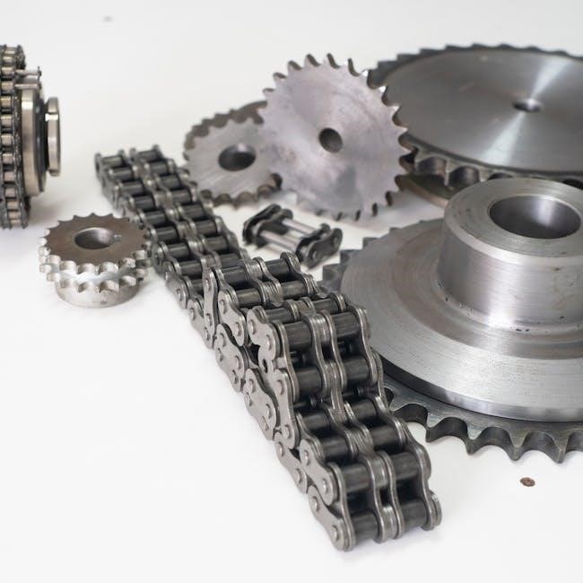
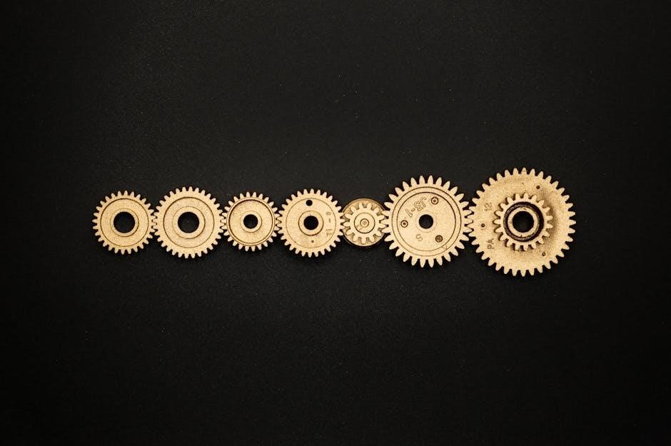
Gears: Types and Functions
Gears are the heart of a manual transmission, responsible for transforming engine power into varying levels of torque and speed. Different gear types fulfill specific roles within the system. Spur gears, characterized by straight teeth, are commonly used for their simplicity and efficiency in transferring power between parallel shafts. Helical gears, featuring angled teeth, offer smoother and quieter operation, reducing noise and vibration, while also handling higher loads.
Bevel gears, with teeth cut on a conical surface, are employed to transmit power between shafts that intersect. Each gear ratio provides a different mechanical advantage, allowing the driver to select the optimal power delivery for various driving conditions. The precise meshing of these gears is critical for efficient power transfer and minimizing wear. Careful design and material selection ensure durability and reliable performance throughout the transmission’s lifespan.
Spur Gears
Spur gears represent a foundational element within manual transmissions, distinguished by their straightforward design featuring straight teeth cut parallel to the axis of rotation. This simplicity translates to efficient power transmission between parallel shafts, making them a cost-effective and reliable choice for many applications. They excel in scenarios demanding direct power transfer without the need for angled drives.
However, spur gears are known for generating more noise during operation compared to helical counterparts, due to the abrupt engagement of their teeth. Despite this, their robust construction and ease of manufacturing ensure widespread use in various gearboxes. Proper lubrication is crucial for minimizing friction and wear, extending their operational life. Their fundamental role in establishing gear ratios makes them indispensable within the broader transmission system.

Helical Gears
Helical gears represent an advancement over spur gears, characterized by teeth cut at an angle to the axis of rotation. This angled design introduces several key benefits, most notably smoother and quieter operation. The gradual engagement of teeth reduces noise and vibration, enhancing the overall driving experience. This progressive contact also distributes load more evenly, increasing gear durability and lifespan.
However, the angled teeth generate axial thrust, requiring the use of thrust bearings to manage these forces. This adds complexity and cost to the system. Despite this, the advantages of reduced noise and increased load capacity often outweigh the drawbacks, making helical gears prevalent in modern manual transmissions. Their efficiency in power transfer and refined operation contribute significantly to vehicle performance and comfort.
Bevel Gears
Bevel gears are distinguished by their conical shape and are specifically designed to transmit power between shafts that intersect, typically at a 90-degree angle. Unlike spur or helical gears which operate on parallel shafts, bevel gears excel in changing the direction of rotation; Several types exist, including straight bevel gears, spiral bevel gears, and hypoid bevel gears, each offering unique characteristics.
Straight bevel gears are simpler to manufacture but generate more noise, while spiral and hypoid gears provide smoother, quieter operation due to their curved teeth and gradual engagement. Hypoid gears, in particular, allow for larger gear ratios and offset shaft configurations. Within a manual transmission, bevel gears are commonly found in the reverse gear mechanism, enabling a change in direction to facilitate backing up. Their robust design ensures reliable power transfer in these critical applications.
Shafts: Input, Output, and Countershaft
Manual transmissions rely on a network of shafts to effectively transfer power from the engine to the wheels. The input shaft directly receives rotational force from the engine’s flywheel, initiating the power flow. Connected to the input shaft are various gears that engage with the countershaft, also known as the lay shaft. This shaft transmits power across the transmission, facilitating different gear ratios.
The output shaft is the final link in the chain, delivering power to the driveshaft and ultimately, the wheels. These shafts are meticulously engineered from high-strength steel alloys to withstand significant torsional stress and fatigue. Proper alignment and support via bearings are crucial for smooth operation and longevity. The precise arrangement and gear ratios on these shafts determine the vehicle’s overall performance characteristics, including acceleration and top speed.
Bearings: Supporting Rotating Parts
Bearings are indispensable components within a manual transmission, playing a critical role in facilitating smooth and efficient rotation of the shafts and gears. These components minimize friction and reduce wear, ensuring reliable power transfer. Several types of bearings are employed, including ball bearings, roller bearings, and tapered roller bearings, each suited for specific load and speed requirements.
They support the input shaft, output shaft, countershaft, and various gears, absorbing radial and axial loads. Proper lubrication is paramount for bearing health, preventing overheating and premature failure. Regular inspection and replacement of worn bearings are essential maintenance procedures. High-quality bearings contribute significantly to the overall durability and performance of the manual transmission, reducing noise and vibration during operation.

Clutch System – The Connection Point
The clutch system expertly manages the power flow between the engine and transmission, utilizing discs and plates for smooth engagement and disengagement.
Clutch Disc & Pressure Plate
The clutch disc, a crucial friction component, is responsible for transmitting engine power to the transmission. It features friction material riveted to a central hub, designed to clamp firmly against the flywheel. This creates the necessary friction for power transfer, enabling vehicle movement.
Complementing the disc is the pressure plate, a spring-loaded mechanism that applies clamping force. When the clutch pedal is released, the pressure plate presses the disc against the flywheel, engaging the transmission. Conversely, depressing the pedal disengages the plate, allowing gear changes.
Proper function relies on both components; wear or damage to either significantly impacts performance. Regular inspection and replacement, as needed, are vital for maintaining a responsive and reliable drivetrain. Understanding their interplay is key to diagnosing clutch-related issues.
Throwout Bearing (Release Bearing)
The throwout bearing, also known as the release bearing, plays a vital role in disengaging the clutch. It’s a critical component positioned between the pressure plate and the clutch fork, facilitating smooth gear changes. When the clutch pedal is depressed, the bearing pushes against the pressure plate, relieving clamping force and allowing the engine to disconnect from the transmission.
This bearing must withstand significant stress and friction during each clutch operation. Consequently, it’s a common wear item, often exhibiting noise or failure over time. Symptoms include squealing sounds when the clutch pedal is pressed or difficulty shifting gears.
Regular inspection and timely replacement are essential to prevent further damage to the clutch system. A failing throwout bearing can lead to complete clutch disengagement failure, necessitating more extensive repairs.
Clutch Master & Slave Cylinders

The clutch master and slave cylinders are hydraulic components essential for transmitting force from the clutch pedal to the clutch fork. The master cylinder, activated by the pedal, pressurizes hydraulic fluid. This pressurized fluid travels through a line to the slave cylinder, located near the transmission.
The slave cylinder then converts hydraulic pressure back into mechanical force, pushing the clutch fork and disengaging the clutch. These cylinders work in tandem to provide smooth and consistent clutch operation. Leaks within either cylinder, or air in the hydraulic line, can result in a spongy pedal feel or complete clutch failure.
Proper bleeding of the hydraulic system is crucial after any maintenance or repair. Regular inspection for leaks and fluid levels is also vital for maintaining optimal clutch performance and preventing costly repairs.
Clutch Fork & Linkage
The clutch fork, a pivotal component, translates the hydraulic pressure from the slave cylinder into linear motion. This motion directly acts upon the throwout bearing, initiating clutch disengagement. A robust linkage system connects the clutch fork to the slave cylinder, ensuring precise and reliable operation.
This linkage can vary in design, ranging from simple direct connections to more complex arrangements utilizing pivot points and levers. Proper adjustment of this linkage is critical for achieving correct clutch pedal free play and full clutch disengagement. Incorrect adjustment can lead to slipping clutches or difficulty shifting gears.
Regular inspection of the clutch fork and linkage for wear, damage, or looseness is essential. Worn components can cause inconsistent clutch performance and potentially lead to transmission damage. Lubrication of pivot points within the linkage also contributes to smooth operation and longevity.

Shifting Mechanism – Controlling Gear Selection
The shifting mechanism precisely engages gears, utilizing linkages, forks, and synchronizers to smoothly transition between speeds for optimal vehicle control.
Shift Linkage: Connecting Lever to Transmission
The shift linkage serves as the crucial intermediary, translating the driver’s gear selection from the shift lever directly to the internal mechanisms within the manual transmission. This system comprises a series of rods, cables, or a combination of both, meticulously engineered to ensure precise and reliable gear engagement.
Its primary function is to transmit the motion of the shift lever, located within the cabin, to the shift forks inside the transmission housing. Different vehicle designs employ varying linkage configurations; some utilize direct mechanical linkages for a more tactile feel, while others opt for cable-operated systems to reduce vibration and improve packaging flexibility.
Proper adjustment and maintenance of the shift linkage are paramount for smooth and accurate gear changes. Any looseness or misalignment within the linkage can result in imprecise shifting, difficulty selecting gears, or even damage to the transmission components. Regular inspection and lubrication are essential to maintain optimal performance and longevity of this vital system.
Shift Forks: Engaging Gears
Shift forks are integral components within a manual transmission, responsible for physically moving the synchronizer sleeves to engage the desired gears. These robust, typically forged metal pieces are directly actuated by the shift linkage, converting linear motion into the precise lateral movement needed for gear selection.
Each gear within the transmission has a corresponding shift fork, carefully designed to interface with the synchronizer hub and sleeve. When the driver initiates a gear change, the shift linkage pushes or pulls on the appropriate shift fork, sliding the synchronizer sleeve into engagement with the selected gear.
The durability and precision of shift forks are critical for reliable transmission operation. Wear or damage to these components can lead to difficulty shifting, gear clash, or complete failure of gear engagement. Regular inspection during transmission service is vital to ensure proper function and prevent costly repairs.
Synchronizers: Smoothing Gear Changes

Synchronizers are arguably the most crucial element in achieving smooth and effortless gear changes within a manual transmission. Their primary function is to equalize the rotational speed of the gear being selected and the main shaft before engagement, preventing grinding and jarring; This is accomplished through friction, bringing the speeds into harmony.
Without synchronizers, shifting gears would be a violent and damaging process. They utilize a complex arrangement of components, including synchronizer rings and hubs, to create the necessary friction. The driver’s skill in timing the clutch engagement complements the synchronizer’s mechanical action.
Properly functioning synchronizers are essential for transmission longevity and driver comfort. Worn synchronizer rings result in difficulty shifting, especially into specific gears, and a noticeable grinding sound. Regular maintenance and timely replacement are key to maintaining optimal performance.
Synchronizer Rings
Synchronizer rings are the heart of the synchronization process, acting as friction surfaces to match the speeds of gears before engagement. Typically constructed from brass or specialized friction materials, these rings are designed to wear over time as they perform their crucial function. They slide along a splined hub, contacting the corresponding cone on the gear being selected.
As the shift lever is moved, the ring is forced against the gear cone, creating friction. This friction gradually equalizes the rotational speeds. Once synchronized, the ring allows for a smooth, clash-free gear engagement. The material composition and design of these rings directly impact shift quality and durability.
Signs of worn synchronizer rings include grinding during shifts, difficulty selecting gears, and a “double-clutching” sensation even when attempting normal shifts. Replacement is often necessary to restore smooth operation.
Synchronizer Hubs
Synchronizer hubs serve as the central component within the synchronizer assembly, providing a sliding connection for the synchronizer rings and facilitating gear engagement. These hubs are typically constructed from durable steel and feature internal splines that allow the rings to move axially during the shifting process. They are directly linked to the shift forks, translating driver input into gear selection.
The hub’s design incorporates grooves or channels to accommodate the synchronizer rings and allows for precise movement. Proper lubrication is critical for smooth operation, reducing friction and wear. Damage to the hub, such as worn splines or cracks, can severely impair shifting performance.
Inspecting the hubs for wear during transmission service is essential. Replacement is often required alongside synchronizer rings to ensure optimal functionality and prevent premature failure of the entire synchronizer assembly.
Auxiliary Components & Systems
Essential systems like fluid lubrication, speed sensors, mounts, and the reverse gear mechanism enhance manual transmission performance and overall vehicle operation.
Transmission Fluid & Lubrication
Transmission fluid is absolutely critical for the longevity and smooth operation of a manual gearbox. Its primary function extends beyond simple lubrication; it actively cools the internal components, reducing friction and wear between the gears, shafts, and bearings. Different manual transmissions require specific fluid types – often GL-4 or GL-5 gear oils – with varying viscosities to ensure optimal performance.
Regular fluid changes are paramount, as degraded fluid loses its lubricating properties and can contribute to component damage. The frequency of these changes depends on driving conditions and manufacturer recommendations. Proper lubrication minimizes heat buildup, prevents corrosion, and ensures efficient power transfer. Ignoring this vital maintenance aspect can lead to costly repairs or even complete transmission failure. Selecting the correct fluid and adhering to a maintenance schedule are key to a reliable manual transmission.
Speed Sensors & Output Shaft Sensors
Modern manual transmissions often integrate speed sensors and output shaft sensors to provide crucial data to the vehicle’s electronic control unit (ECU). These sensors monitor the rotational speed of the transmission’s output shaft, enabling accurate vehicle speed calculations displayed on the dashboard. This information is also vital for various systems, including anti-lock braking (ABS), traction control, and cruise control, ensuring they function correctly.
Output shaft sensors specifically track the transmission’s output speed, aiding in diagnostics and potentially influencing engine management. Malfunctioning sensors can lead to inaccurate speed readings, erratic shifting behavior, or illuminated warning lights. Regular inspection and replacement of these sensors, when necessary, are essential for maintaining optimal vehicle performance and safety. They are key components in the integration of mechanical and electronic systems.
Transmission Mounts & Supports
Transmission mounts and supports are critical, yet often overlooked, components of a manual transmission system. Their primary function is to securely attach the transmission to the vehicle’s chassis, isolating it from vibrations and minimizing noise transmission into the passenger compartment. These mounts typically consist of rubber and metal components designed to absorb shocks and dampen oscillations generated during gear changes and vehicle movement.
Different types of mounts – fluid-filled, solid, or a combination – are used depending on the vehicle’s design and performance requirements. Worn or damaged mounts can cause excessive vibration, clunking noises during shifting, and even damage to surrounding components. Regular inspection of these supports is crucial for maintaining ride comfort, preventing premature wear, and ensuring the longevity of the entire drivetrain system. Proper mounting is essential for smooth operation.
Reverse Gear Mechanism
The reverse gear mechanism within a manual transmission is a unique system designed to change the direction of rotation of the output shaft. Unlike forward gears which utilize a direct drive, reverse gear typically employs an idler gear positioned between the input and output shafts. This additional gear introduces an intermediary step, effectively reversing the rotational direction.
Engaging reverse often requires a specific shift pattern, frequently involving pushing down on the shift lever or moving it to a designated position. Synchronizers are generally not used for reverse, meaning a complete stop is necessary before attempting engagement to avoid gear clash and damage. The mechanism must be robust to withstand the stresses of reversing, particularly under load. Proper functioning ensures safe and controlled maneuvering in tight spaces, a vital aspect of vehicle operation.